Posts

Rocker Arms

The rocker arms transmit the lifting force from the cams  to the valves. Rocker arm assemblies are  supported by a plain, roller, or ball bearing, or a combination  of these, which serves as a pivot. Generally, one end of the  arm bears against the push rod and the other bears on the  valve stem. One end of the rocker arm is sometimes slotted to  accommodate a steel roller. The opposite end is constructed  with either a threaded split clamp and locking bolt or a tapped  hole. The arm may have an adjusting screw, for adjusting  the clearance between the rocker arm and the valve stem tip.The screw can be adjusted to the specified clearance to make  certain that the valve closes fully.
Valve Springs

Each valve is closed by two or three helical springs. If a single  spring were used, it would vibrate or surge at certain speeds. To eliminate this difficulty, two or more springs (one inside the other) are installed on each valve. Each spring vibrates  at a different engine speed and rapid damping out of all  spring-surge vibrations during engine operation results. Two or more springs also reduce danger of weakness and possible  failure by breakage due to heat and metal fatigue. The springs  are held in place by split locks installed in the recess of the  valve spring upper retainer or washer, and engage a groove  machined into the valve stem. The functions of the valve  springs are to close the valve and to hold the valve securely  on the valve seat.

Push Rod

The push rod, tubular in form, transmits the lifting force from  the valve tappet to the rocker arm. A hardened-steel ball is  pressed over or into each end of the tube. One ball end fits into  the socket of the rocker arm. In some instances, the balls are  on the tappet and rocker arm, and the sockets are on the push  rod. The tubular form is employed because of its lightness and  strength. It permits the engine lubricating oil under pressure  to pass through the hollow rod and the drilled ball ends to  lubricate the ball ends, rocker-arm bearing, and valve-stem  guide. The push rod is enclosed in a tubular housing that  extends from the crankcase to the cylinder head, referred to  as push rod tubes

MODULE 16. PISTON ENGINE

Element 16.1 Fundamentals  Mechanical, thermal and volumetric efficiencies; Operating principles — 2 stroke, 4 stroke, Otto and Diesel; Piston displacement and compression ratio; Engine configuration and firing order.                                                                                               Element 16.2 Engine Performance  Power calculation and measurement; Factors affecting engine power; Mixtures/leaning, pre-ignition. 16.3 Engine Construction  Crank case, crank shaft, cam shafts, sumps; Accessory gearbox; Cylinder and piston assemblies; Connecting rods, inlet and exhaust manifolds; Valve mechanisms; Propeller reduction gearboxes

Valve

Valve opens and closes  cylinder ports. The valves used in aircraft engines are  the conventional poppet type. The valves are also typed by  mushroom or tulip. Valve Construction -   valves are subjected  to high temperatures, corrosion, and operating stresses. Intake valves operate at lower temperatures  than exhaust valves, they can be made of chromic-nickel  steel.  Exhaust valves are usually made of nichrome,  silchrome, or cobalt-chromium steel because these materials  are much more heat resistant. Valve head has a ground face that forms a seal against  the ground valve seat in the cylinder head when the valve is  closed.  Face of the valve is usually ground to an angle  of either 30° or 45° . In some engines, the intake-valve face  is ground to an angle of 30°, and the exhaust-valve face is  ground to a 45° angle. Valve faces are often made more  durable by the application of a material called stellite. About  1⁄16 inch of this alloy is welded to the valve face and gr

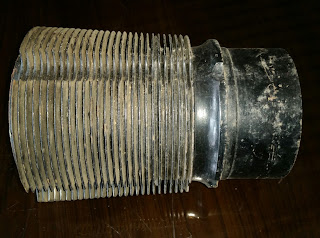
Cylinder Barrel

Image
Cylinder barrel   are  made of light and high-strength material and  have the proper characteristics for  operating under high temperatures. It must be made of a  good bearing material and have high tensile strength.  Cylinder barrel is made of a steel alloy forging with the inner  surface hardened to resist wear of the piston and the piston  rings which bear against it.  Hardening is usually done  by exposing the steel to ammonia or cyanide gas while the steel is very hot. The steel soaks up nitrogen from the gas,which forms iron nitrides on the exposed surface. As a result  of this process, the metal is said to be nitrided.  Nitriding   only penetrates into the barrel surface a few thousands of an  inch. As the cylinder barrels wear due to use, they can be  repaired by chroming. This is a process that plates chromium  on the surface of the cylinder barrel and brings it back to new  standard dimensions.  Chromium-plated cylinders should use  cast iron rings. Honing the cyli

Cylinder Head

Cylinder head   provides a place for  combustion of the fuel/air mixture and to give the cylinder  more heat conductivity for adequate cooling. The fuel/air  mixture is ignited by the spark in the combustion chamber  and commences burning as the piston travels toward TDC  on the compression stroke. The  ignited charge is rapidly expanding at this time, and pressure  is increasing so that, as the piston travels through the TDC  position, it is driven downward on the power stroke. The intake and exhaust valve ports are located in the cylinder  head along with the spark plugs and the intake and exhaust  valve actuating mechanisms. After the cylinder head is cast, the spark plug bushings, valve  guides, rocker arm bushings, and valve seats are installed in  the cylinder head. Spark plug openings may be fitted with bronze or steel bushings that are shrunk and screwed into  the openings.                  Stainless steel Heli-Coil spark plug inserts   are used in many engines currently m