Posts

Showing posts from 2018

Rocker Arms

The rocker arms transmit the lifting force from the cams  to the valves. Rocker arm assemblies are  supported by a plain, roller, or ball bearing, or a combination  of these, which serves as a pivot. Generally, one end of the  arm bears against the push rod and the other bears on the  valve stem. One end of the rocker arm is sometimes slotted to  accommodate a steel roller. The opposite end is constructed  with either a threaded split clamp and locking bolt or a tapped  hole. The arm may have an adjusting screw, for adjusting  the clearance between the rocker arm and the valve stem tip.The screw can be adjusted to the specified clearance to make  certain that the valve closes fully.
Valve Springs

Each valve is closed by two or three helical springs. If a single  spring were used, it would vibrate or surge at certain speeds. To eliminate this difficulty, two or more springs (one inside the other) are installed on each valve. Each spring vibrates  at a different engine speed and rapid damping out of all  spring-surge vibrations during engine operation results. Two or more springs also reduce danger of weakness and possible  failure by breakage due to heat and metal fatigue. The springs  are held in place by split locks installed in the recess of the  valve spring upper retainer or washer, and engage a groove  machined into the valve stem. The functions of the valve  springs are to close the valve and to hold the valve securely  on the valve seat.

Push Rod

The push rod, tubular in form, transmits the lifting force from  the valve tappet to the rocker arm. A hardened-steel ball is  pressed over or into each end of the tube. One ball end fits into  the socket of the rocker arm. In some instances, the balls are  on the tappet and rocker arm, and the sockets are on the push  rod. The tubular form is employed because of its lightness and  strength. It permits the engine lubricating oil under pressure  to pass through the hollow rod and the drilled ball ends to  lubricate the ball ends, rocker-arm bearing, and valve-stem  guide. The push rod is enclosed in a tubular housing that  extends from the crankcase to the cylinder head, referred to  as push rod tubes

MODULE 16. PISTON ENGINE

Element 16.1 Fundamentals  Mechanical, thermal and volumetric efficiencies; Operating principles — 2 stroke, 4 stroke, Otto and Diesel; Piston displacement and compression ratio; Engine configuration and firing order.                                                                                               Element 16.2 Engine Performance  Power calculation and measurement; Factors affecting engine power; Mixtures/leaning, pre-ignition. 16.3 Engine Construction  Crank case, crank shaft, cam shafts, sumps; Accessory gearbox; Cylinder and piston assemblies; Connecting rods, inlet and exhaust manifolds; Valve mechanisms; Propeller reduction gearboxes

Valve

Valve opens and closes  cylinder ports. The valves used in aircraft engines are  the conventional poppet type. The valves are also typed by  mushroom or tulip. Valve Construction -   valves are subjected  to high temperatures, corrosion, and operating stresses. Intake valves operate at lower temperatures  than exhaust valves, they can be made of chromic-nickel  steel.  Exhaust valves are usually made of nichrome,  silchrome, or cobalt-chromium steel because these materials  are much more heat resistant. Valve head has a ground face that forms a seal against  the ground valve seat in the cylinder head when the valve is  closed.  Face of the valve is usually ground to an angle  of either 30° or 45° . In some engines, the intake-valve face  is ground to an angle of 30°, and the exhaust-valve face is  ground to a 45° angle. Valve faces are often made more  durable by the application of a material called stellite. About  1⁄16 inch of this alloy is welded to the valve face and gr

Cylinder Barrel

Image
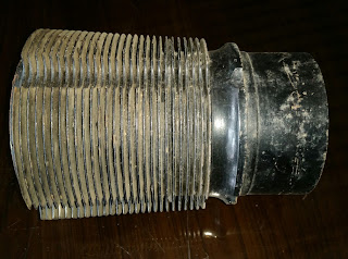
Cylinder barrel   are  made of light and high-strength material and  have the proper characteristics for  operating under high temperatures. It must be made of a  good bearing material and have high tensile strength.  Cylinder barrel is made of a steel alloy forging with the inner  surface hardened to resist wear of the piston and the piston  rings which bear against it.  Hardening is usually done  by exposing the steel to ammonia or cyanide gas while the steel is very hot. The steel soaks up nitrogen from the gas,which forms iron nitrides on the exposed surface. As a result  of this process, the metal is said to be nitrided.  Nitriding   only penetrates into the barrel surface a few thousands of an  inch. As the cylinder barrels wear due to use, they can be  repaired by chroming. This is a process that plates chromium  on the surface of the cylinder barrel and brings it back to new  standard dimensions.  Chromium-plated cylinders should use  cast iron rings. Honing the cyli

Cylinder Head

Cylinder head   provides a place for  combustion of the fuel/air mixture and to give the cylinder  more heat conductivity for adequate cooling. The fuel/air  mixture is ignited by the spark in the combustion chamber  and commences burning as the piston travels toward TDC  on the compression stroke. The  ignited charge is rapidly expanding at this time, and pressure  is increasing so that, as the piston travels through the TDC  position, it is driven downward on the power stroke. The intake and exhaust valve ports are located in the cylinder  head along with the spark plugs and the intake and exhaust  valve actuating mechanisms. After the cylinder head is cast, the spark plug bushings, valve  guides, rocker arm bushings, and valve seats are installed in  the cylinder head. Spark plug openings may be fitted with bronze or steel bushings that are shrunk and screwed into  the openings.                  Stainless steel Heli-Coil spark plug inserts   are used in many engines currently m

Piston Ring

Piston rings prevent leakage of gas pressure from the  combustion chamber and reduce to a minimum the seepage  of oil into the combustion chamber.  The rings  fit into the piston grooves but spring out to press against the  cylinder walls; when properly lubricated, the rings form an  effective gas seal. Piston Ring Construction  are made of high-grade cast iron  ground to  the cross-section desired. Then they are split so that they can  be slipped over the outside of the piston and into the ring  grooves that are machined in the piston wall.  Since their  purpose is to seal the clearance between the piston and the  cylinder wall, they must fit the cylinder wall snugly enough  to provide a gastight fit. They must exert equal pressure at  all points on the cylinder wall, and must make a gas tight fit  against the sides of the ring grooves. Gray cast iron is most often used in making piston rings.  In  some engines, chrome-plated mild steel piston rings are used  in the top compr

Cylinder

Image
Cylinder -  The portion of the engine in which the power is developed  is called the cylinder provides  a combustion chamber where the burning and expansion of  gases take place, and it houses the piston and the connecting  rod.  Cylinder head of an air cooled engine is generally made of  aluminum alloy because aluminum alloy is a good conductor  of heat and its light weight reduces the overall engine weight. Cylinder heads are forged or die-cast for greater strength. The  inner shape of a cylinder head is generally semispherical.  The semispherical shape is stronger than conventionalist  design and aids in a more rapid and thorough scavenging of  the exhaust gases Cylinder used in the air cooled engine is the overhead  valve type.    Each cylinder is an assembly of two  major parts:   cylinder head and  cylinder barrel.  At assembly,  the cylinder head is expanded by heating and then screwed  down on the cylinder barrel, which has been chilled. When  the head cools an

Tappet Assembly

Tappet assembly consists of: 1. A cylindrical tappet, which slides in and out in a tappet  guide installed in one of the crankcase sections around  the cam ring; 2. A tappet roller, which follows the contour of the cam  ring and lobes; 3. A tappet ball socket or push rod socket; and 4. A tappet spring. Function -  to convert the rotational  movement of the cam lobe into reciprocating motion  and to  transmit this motion to the push rod, rocker arm, and then  to the valve tip,  opening the valve at the proper time. The  purpose of the tappet spring is to take up the clearance  between the rocker arm and the valve tip to reduce the shock  load when the  valve is opened. A hole is drilled through the  tappet to allow engine oil to flow to the  hollow push rods to  lubricate the rocker assemblies Solid Lifters/Tappets Solid lifters or cam followers generally require the valve  clearance to be adjusted manually by adjusting a screw and  lock nut. Valve clearance is needed to as

Piston Pin

Piston pin joins the piston to the connecting rod, machined in the form of a tube from a nickel steel alloy forging, casehardened and ground. Piston pin ( wrist pin )  used in modern aircraft  engines is the full-floating type, so called because the pin is  free to rotate in both the piston and in the connecting rod piston-pin bearing.  Piston pin must be held in place to  prevent the pin ends from scoring the cylinder walls.  A plug  of relatively soft aluminum in the pin end provides a good  bearing surface against the cylinder wall.

Piston

Image
Piston is a cylindrical member which moves back and forth within a steel cylinder. The piston acts as a moving wall within the combustion chamber.  As the piston moves down in the cylinder, it draws in the fuel/air mixture. As it moves upward,  it compresses the charge, ignition occurs, and the expanding gases force the piston downward. This force is transmitted to the crankshaft through the connecting rod. On the return upward stroke, the piston forces the exhaust gases from the cylinder and the cycle repeats. Pistons are machined from aluminum alloy forgings. Grooves are machined in the outside surface of the piston to receive the piston rings, and cooling fins are provided on the inside of the piston for greater heat transfer to the engine oil. Pistons may be either the trunk type or the slipper type. T op of the piston , or head, may be flat, convex, or concave. Recesses may be machined in the piston head to prevent interference with the valves. Modern engines use cam gro

Connecting Rod

Connecting rod is the link that transmits forces between the piston and the crankshaft is strong enough to remain rigid under load and yet be light enough to reduce the inertia forces that are produced when the rod and piston stop, change direction, and start again at the end of each stroke. There are four types of connecting-rod assemblies  1. Plain 2. Fork and blade 3. Master and articulated 4. Split-type

Crankshaft

Image
Crankshaft is carried in a position parallel to the longitudinal axis of the crankcase and is generally supported by a main bearing between each throw.The crankshaft main bearings must be supported rigidly in the crankcase. Crankshaft is the backbone of the  engine transform the reciprocating motion of the piston and connecting rod into rotary motion for rotation of the propeller. Crankshaft is a shaft composed of one or more cranks. The cranks, or throws, are formed by forging offsets into a shaft before it is machined.  Crankshafts ( very strong)  forged from a very strong alloy, such as chromium-nickel-molybdenum steel may be of single-piece or multi piece construction. Crankshaft has three main parts—a journal , crankpin , and crank cheek . Counterweights and dampers are usually attached to it to reduce engine vibration.  Journal is supported by, and rotates in, a main bearing. It serves as the center of rotation of the crankshaft. It is surface hardened to reduce we

Crankcase Sections

Image
Crankcase is  foundation of an engine.  It contains  the bearings and bearing supports in which the crankshaft  revolves.  C rankcase  supporting itself and  provide a tight enclosure for the lubricating oil and  various external and internal mechanisms of the  engine. Provides support for attachment of the  cylinder assemblies, and the powerplant to the aircraft.  Rigid and strong to prevent misalignment  of the crankshaft and its bearings.  Made of Cast or forged aluminum  alloy   because  it is light and strong.  Crankcase is subjected to many  variations of mechanical loads and other forces. Since the  cylinders are fastened to the crankcase, the tremendous  forces placed on the cylinder tend to pull the cylinder  off the crankcase. The unbalanced centrifugal and inertia  forces of the crankshaft acting through the main bearings  subject the crankcase to bending moments which change  continuously in direction and magnitude. The machined surfaces on which the cylinders a

Reciprocating Engines - Design and Construction

Image
The basic major components of a reciprocating engine are Crankcase,  Cylinders,  Pistons,  Connecting rods,  Valves,valve-operating mechanism,  Crankshaft.  In the head of each cylinder are the valves and spark plugs.  One of the valves is in a passage leading from the induction system; the other is in a passage leading to the exhaust system. Inside each cylinder is a movable piston connected to a crankshaft by a connecting rod.

Aircraft Engine

Image
Classification -Aircraft engines can be classed by operating cycles, cylinder arrangement, or the method of thrust production. Heat engines -  convert fuel into heat energy that is converted to mechanical energy to produce thrust. Most of the current aircraft engines Internal combustion - the combustion process takes place inside the engine. Reciprocating engine s is classified by cylinder arrangement (in line,V-type, radial, and opposed) or according to the method of cooling (liquid cooled or air cooled). Air-cooled engines-  heat transfer is direct from the cylinders to the air by thin metal fins on the cylinders  in order to have increased surface for sufficient heat transfer. Inline Engine - one bank of even number of cylinders arranged inline has only one crank shaft, which is located either above or below the cylinders. If the engine is designed to operate with the cylinders below the crankshaft, it is called an inverted engine The inline engine has a small frontal